FBP | Focus Beam Profiler for Laser Additive Manufacturing
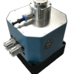
Industrial High Power Laser Beam Profiler The Focus-Beam-Profiler HP-FBP-fix presents
Industrial High Power Laser Beam Profiler The Focus-Beam-Profiler HP-FBP-fix presents
RayCi Software for Beam Profilers RayCi is a dedicated laser
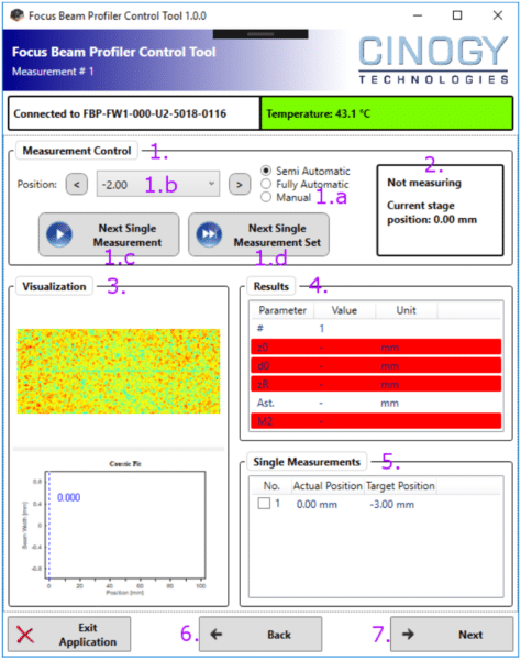
This application note focuses on using focus beam profiler for laser additive manufacturing and answering the following questions. Where is my beam focusing? How big is my spot? Is it stable in time?
Selective laser sintering (SLS) is an additive manufacturing (AM) technique that uses a laser as the power source to sinter powdered material (typically nylon or polyamide), aiming the laser automatically at points in space defined by a 3D model, binding the material together to create a solid structure. It is similar to Selective Laser Melting (SLM); the two are instantiations of the same concept but differ in technical details. Selective laser melting (SLM) uses a comparable concept, but in SLM the material is fully melted rather than sintered, allowing different properties (crystal structure, porosity, and so on).
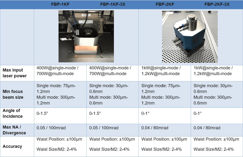
Those processes require uniform, symmetrical and stable power density distribution of the laser beam. More specifically, the focus spot size and intensity have to be maintained within a finite acceptance range throughout each build. Because of the high power of the laser used (typically in the range of several 100s of Watts to kW, thermal lensing can occur and affect the focus position in time. Therefore, understanding the stability of this parameter is critical in order to avoid structural weakness captured stress during the building process.
The Focus Beam Profiler (FBP) is a proven solution developed by Cinogy Technologies hand-in-hand with major actors in the industry. The Focus Beam Profiler is a robust industrial system designed to directly image the high-power on a 2D focal plane array after being attenuated with passive optical components. The position of the measurement plane is calibrated and known with high accuracy, thus giving a direct overview what the beam looks like at that position.
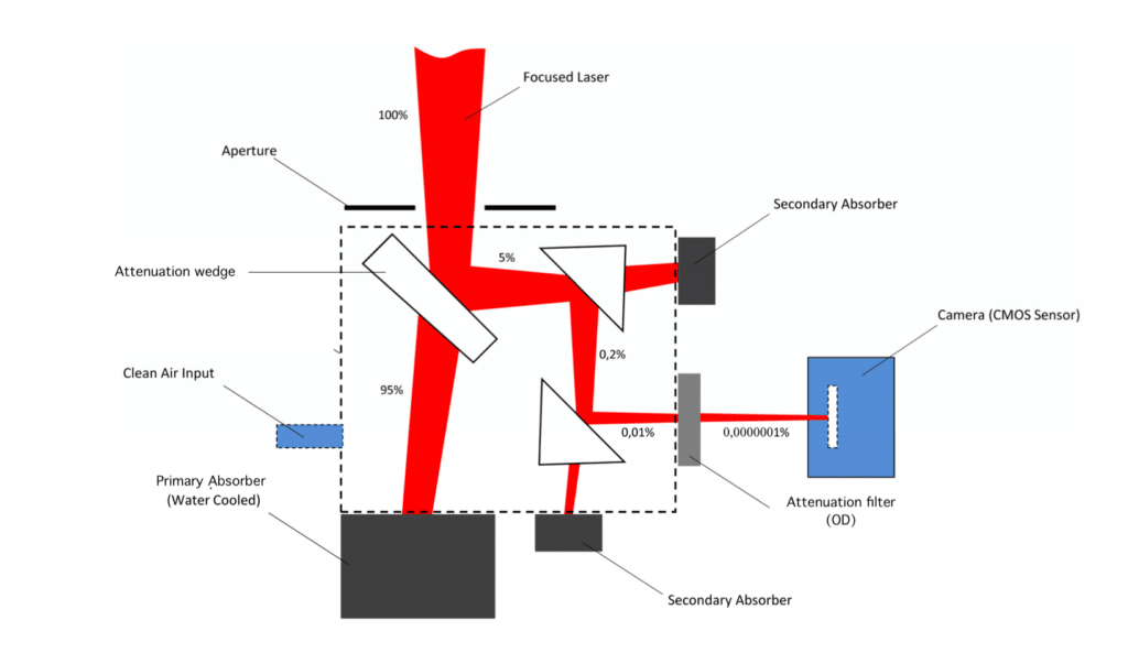
After positioning the Focus Beam profiler onto the build-plate and directly under the path of the laser beam, a complete beam caustic can be acquired by changing the build-plate position. The software quickly outputs the beam parameters according to ISO standard 11146-1 (a detailed description of the method used can be found in our application page.
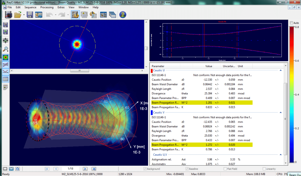
Top-left corner: 2D profile of the beam at selected position. Dotted line delimitates the active area of the beam. Red and blue lines show the beam orientation in beam coordinates (U,V), as opposed to lab coordinates (x,y).
Bottom-left corner: 3D view of the beam caustic. Top-right corner: beam size (y-axis) along the beam path (x-axis). Red and blue lines correspond to the beam coordinate system (U,V). The continuous vertical lines indicate the position of the beam waist (U,V). Note that in this case the beam shows some astigmatism. Bottom-right corner: Numerical data computed from the beam caustic.
Output parameters include: