
What is Free-Space Optics (FSO)?
Free-space optics (FSO) is a line-of-sight communication technology that sends data on a beam of light through open space: the air between two rooftops, the vacuum between satellites, or the path from a ground station to orbit. FSO carries data, voice, and video at several gigabits per second without fiber-optic cable and without a spectrum license, which makes it a practical alternative to radio relay links and a fast way to add optical bandwidth where laying fiber is slow or impossible.
780 to 1600 nmTypical operating wavelength band
300 m to 5 kmTypical terrestrial link, with 8 to 11 km possible
Multi-Gb/sUp to 100 Gb/s when paired with adaptive optics
No licenseNo spectrum license and no trenching
Conceptually, FSO is fiber-optic transmission with the glass taken away. Light from a laser or a light emitting diode (LED) is modulated with data through electrical-to-optical (E/O) conversion, sent across the free-space channel, collected by receiver optics, and converted back into an electrical signal (O/E conversion). Because light travels at almost its vacuum speed in air, roughly 1.5 times faster than in silica fiber, a free-space link also has a small latency advantage over an equivalent run of fiber.
The three building blocks of an FSO link
1
Transmitter
A laser or LED source, modulated with the data stream, launches the beam toward the receiver. Lasers dominate longer links because their narrow divergence keeps more power on target.
2
Free-space channel
The atmosphere absorbs and scatters part of the beam, following the Beer-Lambert law, while turbulent eddies driven by temperature variations distort and bend it. Clouds, fog, rain, smoke, gases, and aerosols all play a role.
3
Receiver
A telescope or lens collects the light and focuses it onto a photodetector or into an optical fiber. High-capacity receivers inject the light into single-mode fiber, which is exactly where turbulence does the most damage and where adaptive optics pays off.
FSO compared with fiber and RF links
| Free-space optics | Fiber | RF / microwave | |
|---|---|---|---|
| Medium | Light through air or space | Light in glass | Radio waves through air |
| Licensing | No spectrum license | Rights-of-way and permits | Licensed spectrum in most bands |
| Deployment | Days: mount and align terminals | Weeks to months of civil works | Days to weeks |
| Interception | Narrow beam, hard to intercept | Requires physical access | Broad beam, easier to intercept |
| Main limits | Fog, turbulence, alignment | Cost and time to install | Spectrum congestion |
Link scales: from chip-to-chip to deep space
- Chip-to-chip communication
- Indoor infrared (IR) and visible light communication (VLC)
- Inter-building links
- Free-space laser communications for airborne, spaceborne, and deep-space missions
Where FSO is used
FSO applications by sector
Metro network extensions
Carriers extend existing metropolitan fiber rings and connect new networks without new trenching.
Backhaul
FSO carries cellular traffic from antenna towers back to facilities wired into the public switched telephone network.
Last-mile access
Many city buildings still have no direct fiber connection because fiber arrived long after they were built. FSO connects these end users to service providers or to existing networks at gigabit speeds.
Service acceleration
Customers get service immediately while their permanent fiber infrastructure is being laid.
Fiber backup
A redundant FSO link backs up fiber in place of a second fiber run.
Enterprise connectivity
FSO links install quickly, which makes them a natural way to connect LAN segments in buildings separated by public streets or other right-of-way property.
Point-to-point line-of-sight links
Dedicated optical links between sites for telecommunication and computer networking.
Temporary networks
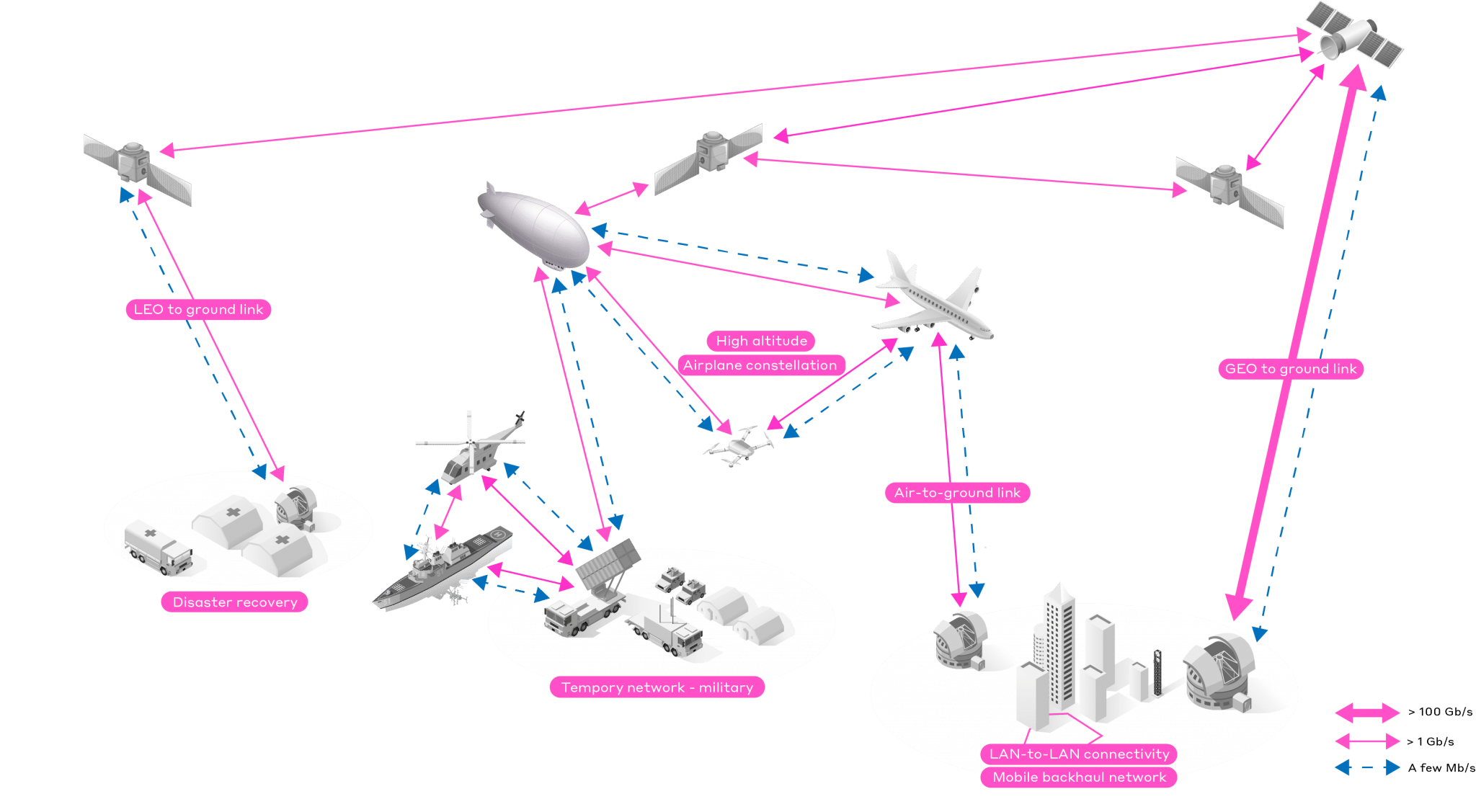
Fast-to-deploy links for events, temporary installations, and disaster recovery.
Inter-satellite links
Optical links between spacecraft, including the elements of a satellite constellation.
Ground-to-satellite links
Laser links between optical ground stations and satellites, where adaptive optics at the ground telescope corrects the turbulence near the ground.
Airborne and deep-space missions
Free-space laser communications for airborne platforms, spaceborne assets, and deep-space probes.
Military applications
Low electromagnetic emanation makes FSO attractive for transferring sensitive data, including for air forces.
Security applications
A narrow, precisely aimed beam is far harder to intercept than a broadcast RF signal.
Atmospheric Turbulence Mitigation Using Adaptive Optics
Adaptive optics (AO) removes the effect of air turbulence to improve coupling efficiency into the receiver’s optical fiber. Typically, an AO system delivers an optical gain of at least 10x on the flux injected into the fiber, which can translate into a tenfold increase in link capacity.
Fiber coupling is where turbulence hurts most. High-data-rate receivers inject the incoming light into single-mode fiber, whose guided mode is only about 10 µm across at 1550 nm. A telescope can focus light into a spot that small only when the incoming wavefront is flat. Turbulence wrinkles the wavefront, the focal spot breaks into speckle far larger than the core, and most of the light misses the fiber.
See the correction loop in action
Loop open. The deformable mirror sits flat, so the turbulent wavefront passes through uncorrected. The focal spot breaks into speckle around the fiber core and only a small fraction of the light is coupled.
Loop closed. The wavefront sensor measures the distortion, the controller computes the correction, and the deformable mirror takes the opposite shape. The wavefront leaving the mirror is flat, the spot collapses onto the core, and the coupled flux rises sharply.
Schematic for illustration, not to scale.
How the correction loop works
As shown in the diagram below, adaptive optics systems rely on three components working together to measure and correct air turbulence in real time.
1
Measure
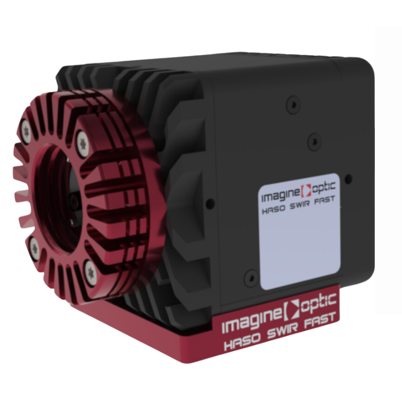
A high-speed wavefront sensor, such as HASO SWIR FAST (1000 to 1700 nm, up to 4.5 kHz), measures the distortion in the incoming beam.
2
Compute
Real-time control electronics convert each measurement into commands for the corrector.
3
Correct
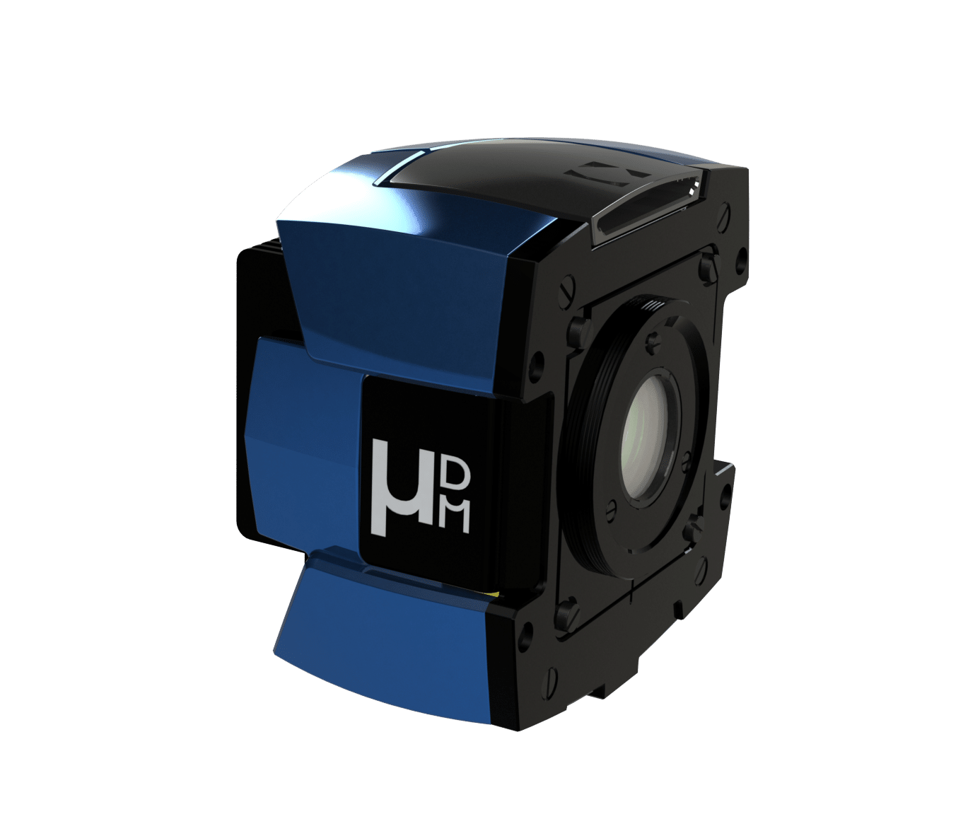
A deformable mirror (DM) reshapes its surface to cancel the distortion, fast enough to keep up with turbulence that changes on millisecond timescales.
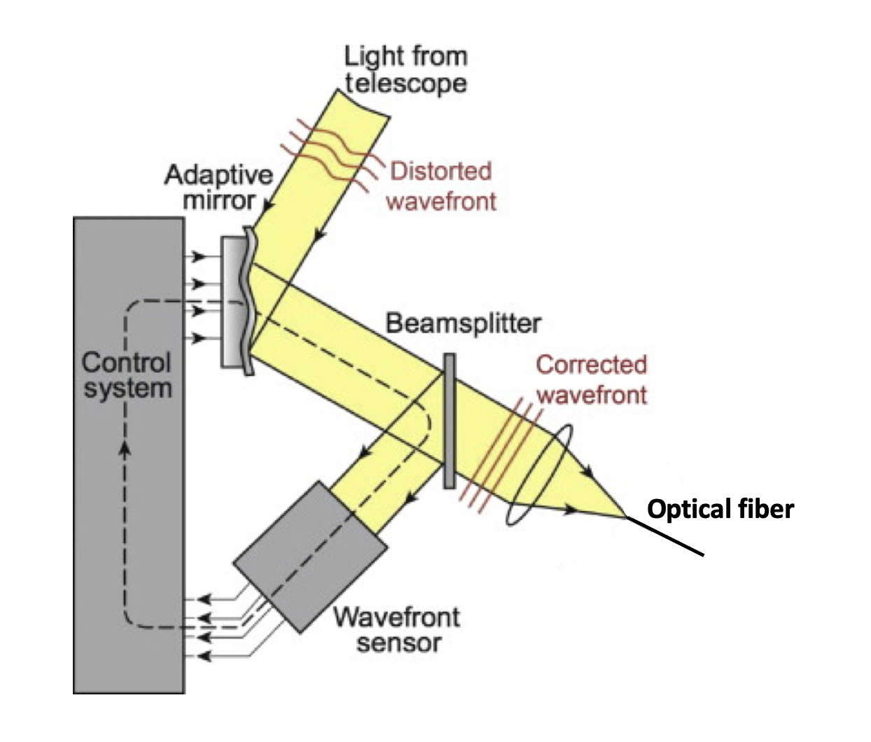
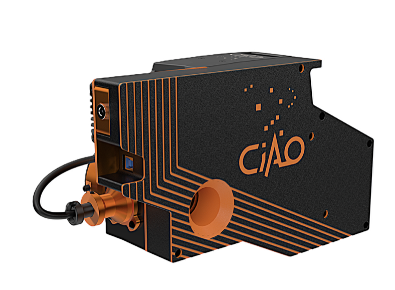
Our partner Imagine Optic offers a standard turnkey system called CIAO SWIR that integrates all of these components into a telescope-compatible package. CIAO SWIR was designed with affordability in mind and is based on an efficient, fast combination of deformable mirror, wavefront sensor, and software.
CIAO SWIR for Free-Space Optics (FSO) and SATCOM
With CIAO SWIR, only a few steps are needed to improve your FSO signal:
- Connect the device to your telescope.
- Plug in the fiber.
- Switch on the system.
- Run the automatic calibration.
- Collect the corrected signal at the output of the fiber.
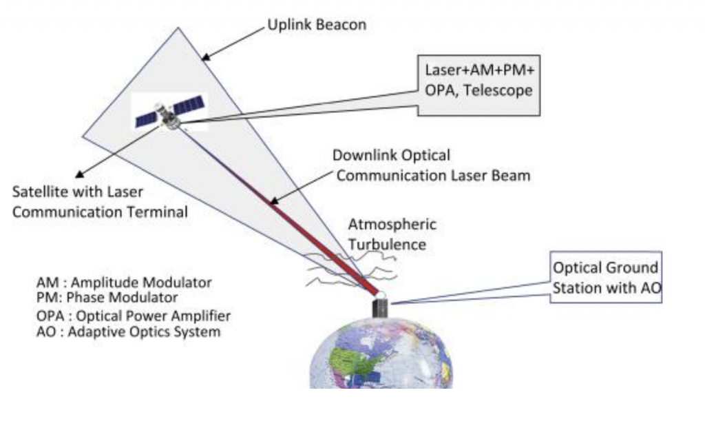
Why optical links for satellite communications
RF frequency bandwidth is saturating, so new methods of communication are needed. RF signals are also broadband, which makes satellite-transmitted information easier to intercept. Laser links can precisely target a station and transmit data in a highly secure way, which makes them ideal for military and security applications. Optical waves can also reach extremely high data rates, up to 100 Gb/s, when paired with adaptive optics. To decode the information, however, the laser light must be injected into a single-mode fiber, and that is the step adaptive optics protects.
First results: fiber injection on a telescope
5xmore photons at the fiber outputOn-sky test, 355 mm telescope, poor seeing (2.2 arcsec)
35 dB to <10 dBsignal loss without vs. with AOLab atmosphere emulator, in partnership with Nokia
10x or moretypical optical gain on injected fluxAdaptive optics for FSO receivers
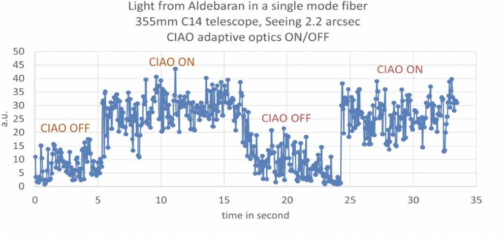
The signal, acquired with an avalanche photodiode, is proportional to the flux injected into the single-mode fiber. By alternating between opening and closing the AO loop, the gain from the improved point spread function (PSF) can be quantified directly. The first injection test on a 355 mm diameter telescope under poor seeing conditions (2.2 arcsec) showed a gain of 5 in the number of photons at the fiber output.
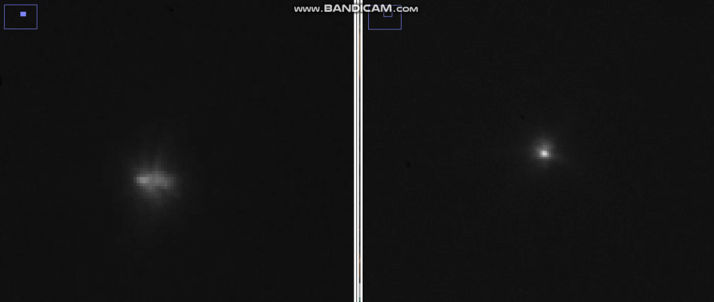
Another very interesting result is the measurement of signal transmission through the atmosphere, both with and without adaptive optics:
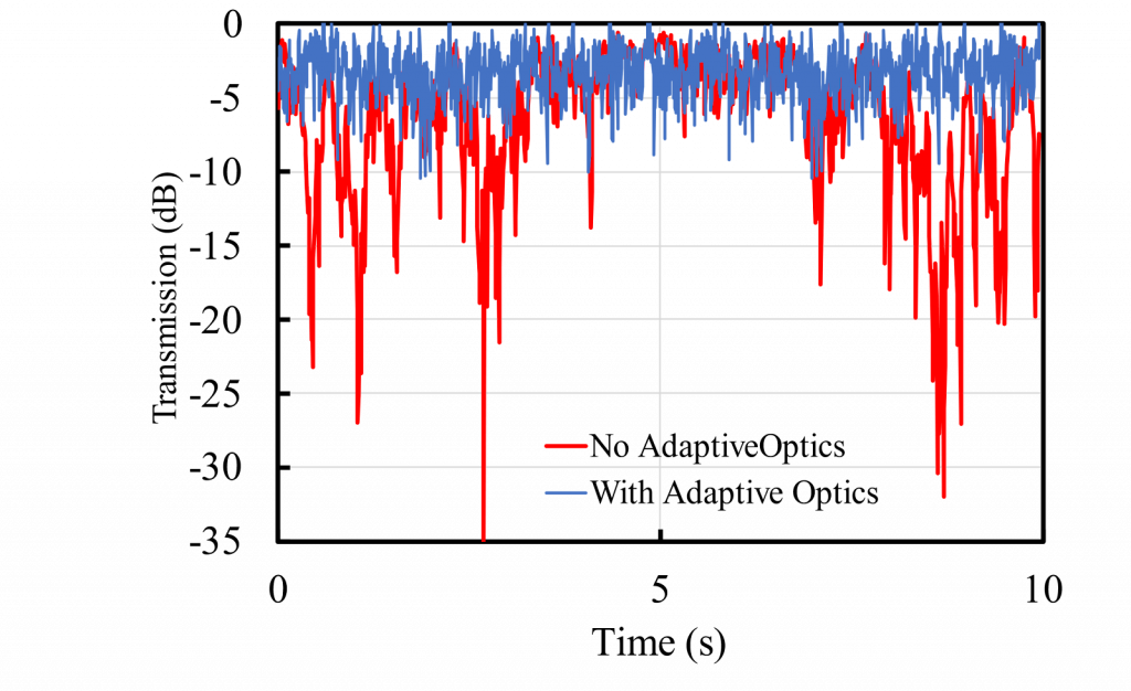
Thanks to a partnership with Nokia, this was simulated in the lab using an atmosphere emulator. Signal losses reached up to 35 dB without adaptive optics. With adaptive optics, losses were reduced to less than 10 dB. That 25 dB improvement means roughly 300 times more optical power reaching the receiver.
CIAO also exists in a visible version, allowing astronomers to do high-resolution imaging: more about CIAO.
Planning an FSO link or an optical ground station? Axiom Optics applications engineers can help you size the telescope, wavefront sensor, and deformable mirror for your link.
Contact Axiom OpticsFrequently asked questions
What is free-space optical communication?
Free-space optical (FSO) communication transmits data on a beam of light through air, space, or vacuum instead of through fiber-optic cable. It provides multi-gigabit line-of-sight links without a spectrum license, typically over 300 m to 5 km on the ground and much longer distances between satellites.
What wavelengths do FSO links use?
Most FSO links operate between 780 and 1600 nm. The 1550 nm band is common for longer links because it shares components with fiber telecom networks and allows higher eye-safe transmit power.
Can adaptive optics compensate for fog?
No. Fog and haze scatter light out of the beam, which is a loss of power rather than a distortion of the wavefront. Adaptive optics corrects turbulence-induced wavefront errors, so fog has to be handled with link margin, shorter hops, or a backup path.
How much does adaptive optics improve an FSO link?
An adaptive optics system typically delivers an optical gain of at least 10x on the flux injected into the receiver fiber. In an on-sky test on a 355 mm telescope in poor seeing (2.2 arcsec), CIAO SWIR increased the photons at the fiber output by a factor of 5, and in a lab atmosphere emulator built with Nokia, signal losses of up to 35 dB without adaptive optics fell below 10 dB with it.
What is CIAO SWIR?
CIAO SWIR is a turnkey adaptive optics system from Imagine Optic, available through Axiom Optics, that combines a deformable mirror, a fast SWIR wavefront sensor, and control software in a telescope-compatible package for FSO and SATCOM ground stations.
How fast does an adaptive optics loop for FSO need to run?
Atmospheric turbulence changes on millisecond timescales, so the correction loop has to run at kilohertz rates to keep up. The HASO SWIR FAST wavefront sensor measures at up to 4.5 kHz across 1000 to 1700 nm.